Introducción a la electrónica II
Analog Digital
To allow our devices to be aware of their surroundings we use sensors that translate the information of the enviroment in electric signals. This signals are normally analog, and because the electronic systems (mostly microcontrollers) we use to process this information and take descitions live mostly in digital world we need to translate analog values in digital ones.
To express or actuate in the real world our devices need to do the oposite: convert our digital information in analog outputs (leds, motors, etc)
Our world is analog, it has an infinite number of values for light, sound, etc. Digital signals are finite, depending on the resolution we use we have more or less values. Ploting signals against time let us understand them Digital binary signals only have two posible values:

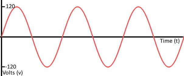
Analog signal plots are smooth:
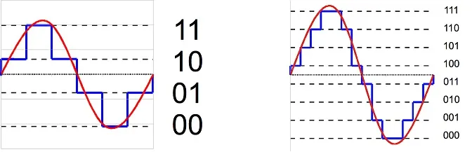
Digitaly encoded signals are discrete representation of analog values with step that vary their size depending on the resolution:

Depending on the amount of bits we use we have a more precise curve.
Converting the analog world to digital: The ADC *
Arduino analogRead() function. ADC resolution: Arduino uno 10 bits -> 1024 different values. Converting digital value to a voltage:
| digital value | voltage | formula |
|---|---|---|
| 1023 | 5v | 5 / (1023/1023) |
| 512 | 2.5v | 5 / (1023/512) |
| 256 | 1.25v | 5 / (1023/256) |
| 128 | 0.625 | 5 / (1023/128) |
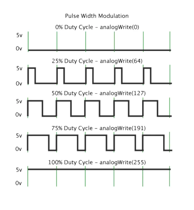
From digital to analog: PWM
Como el Arduino sólo puede tener dos valores posibles como outputs (LOW y HIGH) la única manera de emitir un valor análogo es alternar la salida entre LOW y HIGH a una velocidad suficientemente alta como para que no alcancemos a ver los cambios, y lo que vemos es el promedio de los dos valores.
Input analógico
Leyendo un potenciometro con analogRead()

void setup() {
Serial.begin(115200);
}
void loop() {
int value = analogRead(A0);
Serial.println(value);
delay(50);
}
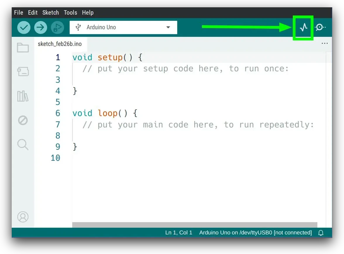
Para poder ver los datos que nos envía el Arduino podemos utilizar el Serial Plotter, haciendo click en el botón de la gráfica que tenemos arriba a la derecha:
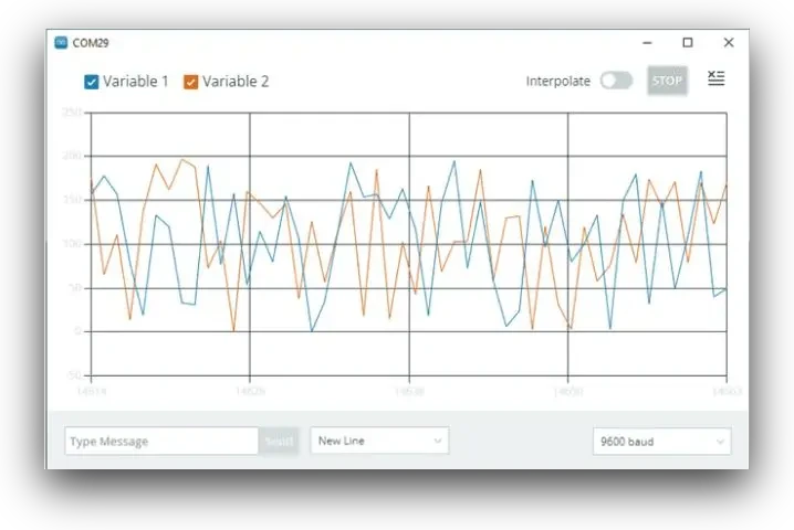
Puedes encontrar más información sobre el uso del serial plotter en la documentación de Arduino.
Output analógico
Usar PWM para hacer fade con un led utilizando la función analogWrite()

int ledPin = 9;
int bright = 0;
int fadeAmount = 5;
void setup() {
pinMode(ledPin, OUTPUT);
}
void loop() {
analogWrite(ledPin, bright);
bright = bright + fadeAmount;
if (bright >= 255 || bright <= 0) {
fadeAmount = -fadeAmount;
}
delay(30);
}
Input y output analógico

int ledPin = 9;
void setup() {
pinMode(ledPin, OUTPUT);
}
void loop() {
int val = analogRead(A0);
analogWrite(ledPin, val / 4);
}
Sensores
Introducción a conceptos de Sensores.
Luz
Light dependant resistor

void setup() {
pinMode(A0, INPUT);
Serial.begin(115200);
}
void loop() {
int light = analogRead(A0);
Serial.println(light);
delay(50);
}

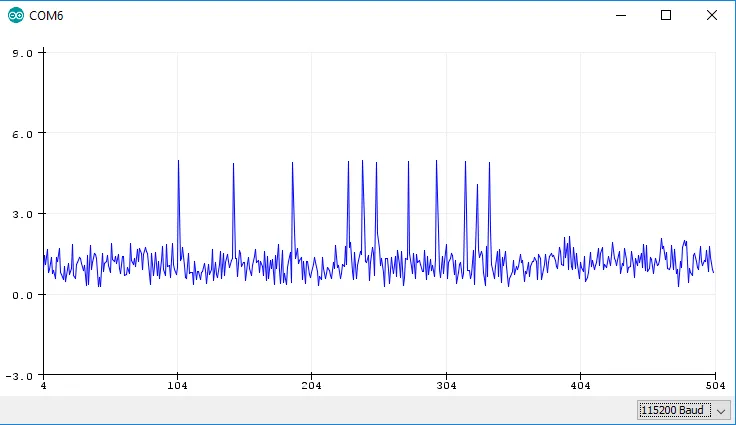
Sonido
Microphone

void setup() {
pinMode(A0, INPUT);
Serial.begin(115200);
}
void loop() {
int noise = analogRead(A0);
Serial.println(noise);
delay(50);
}
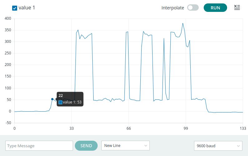
Touch
Averigua qué son las librerías y cómo instalarlas aquí
Primero que nada hay que instalar la librería ADCTouch para Arduino.
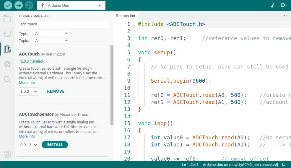
Este circuito es el más sencillo que hemos hecho hasta ahora!!

#include <ADCTouch.h>
int ref0; //reference values to remove offset
void setup() {
Serial.begin(9600);
ref0 = ADCTouch.read(A0, 500); //create reference values to
}
void loop() {
int value0 = ADCTouch.read(A0);
value0 -= ref0; //remove offset
Serial.println(value0); //send actual reading
delay(100);
}
Posición
Ultrasonic sensor

// Define pin's number
#define echoPin 8 // Pin number connected to Echo
#define trigPin 7 // Pin number connected to Trigger
// defines variables
long duration; // variable for the duration of sound wave travel
int distance; // variable for the distance measurement
void setup() {
pinMode(trigPin, OUTPUT);
pinMode(echoPin, INPUT);
Serial.begin(115200);
}
void loop() {
// Clears the trigPin condition
digitalWrite(trigPin, LOW);
delayMicroseconds(2);
// Sets the trigPin HIGH (ACTIVE) for 10 microseconds
digitalWrite(trigPin, HIGH);
delayMicroseconds(10);
digitalWrite(trigPin, LOW);
// Reads the echoPin, returns the sound wave travel time in microseconds
duration = pulseIn(echoPin, HIGH);
// Calculating the distance
distance = duration * 0.034 / 2; // Speed of sound wave divided by 2 (go and back)
// Displays the distance (in cm) on the Serial Monitor
Serial.println(distance);
delay(100);
}
Actuadores
Sonido
Some Music Piano con Comunicación Serial por USB

int buzzPin = 6;
int noteNum = 7;
char keys[] = {'d','r','m','f','s','l','i'};
int freq[] = {262,294,330,369,391,440,493};
void setup() {
pinMode(buzzPin, OUTPUT);
Serial.begin(115200);
}
void loop() {
if (Serial.available()) {
char n = Serial.read();
if (n == '.') noTone(buzzPin);
else {
for (int i=0; i<noteNum; i++) {
if (n == keys[i]) {
tone(buzzPin, freq[i]);
Serial.println(keys[i]);
}
}
}
delay(200);
}
}
/*
* d-do 262
* r-re 294
* m-mi 330
* f-fa 369
* s-sol 391
* l-la 440
* s-si 493
*/
// La cucaracha
// d.d.d.f..l..d.d.d.f..l..f.f.m.m.r.r.ddd..d.d.d.mm.s.
Movimiento
Servomotores

#include <Servo.h>
int servoPin = 9;
int angle = 0;
Servo servo;
void setup() {
servo.attach(servoPin);
}
void loop() {
// scan from 0 to 180 degrees
for(angle = 0; angle < 180; angle++) {
servo.write(angle);
delay(15);
}
// now scan back from 180 to 0 degrees
for(angle = 180; angle > 0; angle--) {
servo.write(angle);
delay(15);
}
}
Luz
Addressable leds Adafruit Uber Guide
Instalar la librería Neopixel

Para probar se puede cargar el ejemplo Strandtest de la librería de Neopixel. Solamente hay que modificar el Pin al que conectamos los datos de los leds y el numero de leds que vamos a controlar.
Para calcular la energía total que le debemos proveer a nuestra tira de leds tenemos que calcular 20mAh x led:
300 leds = 300 x 20mAh = 6000mAh = 6 Amperios
El arduino puede proveer por el pin de 5v 500mAh, esto quiere decir que podemos darle energía a alrededor de 25 leds sin tener problemas.
Ejemplo para la tira completa con un led moviendose a lo largo.
#include <Adafruit_NeoPixel.h>
#define LED_PIN 6
#define LED_COUNT 20
Adafruit_NeoPixel strip(LED_COUNT, LED_PIN, NEO_GRB + NEO_KHZ800);
void setup() {
strip.begin();
strip.show();
strip.setBrightness(128); // Set BRIGHTNESS to about 1/5 (max = 255)
}
void loop() {
for(int i=0; i<strip.numPixels(); i++) {
strip.clear();
strip.setPixelColor(i, 0, 50, 255);
strip.show();
delay(20);
}
}
From ideas to code
Funciones básicas de Arduino
-
Internal arduino functions
-
Herramientas en programación
- Condicionales
- Loops
Lenguajes de programación
Alto y bajo nivel
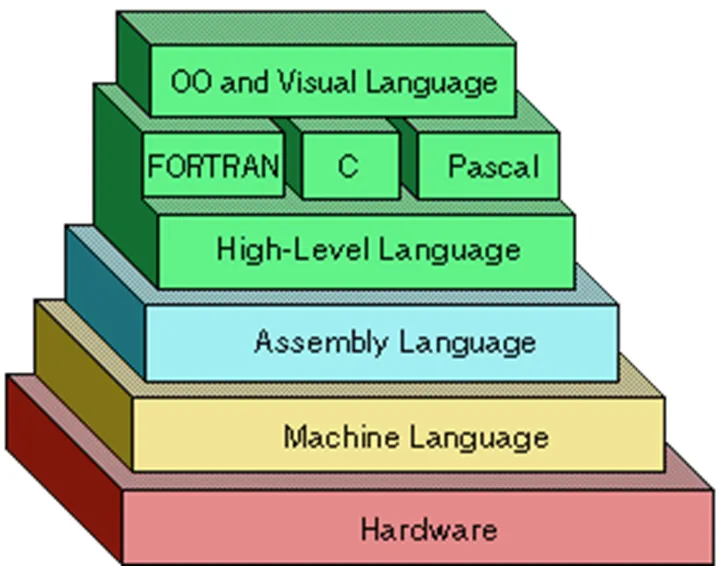
Compilados e interpretados
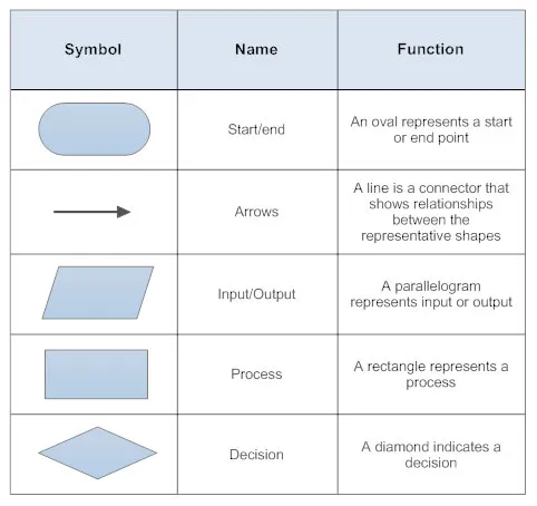
Algoritmos y diagramas de flujo
Un Algoritmo es un conjunto de instrucciones o reglas definidas y no-ambiguas, ordenadas y finitas que permite, típicamente, solucionar un problema, realizar un cómputo, procesar datos y llevar a cabo otras tareas o actividades. Dados un estado inicial y una entrada, siguiendo los pasos sucesivos se llega a un estado final y se obtiene una solución.
Representacion de algoritmos en diagramas de flujo.
Ejemplo de un algoritmo para buscar algo.
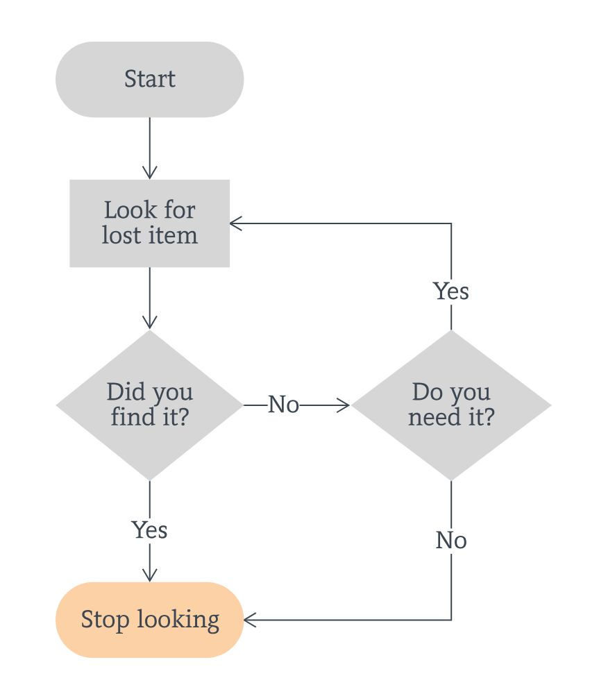
Ejercicio Dibujar el diagrama de flujo y escribir el código:
- Push button y led
- Si el led está apagado: al picar el botón se enciende.
- Si el led está prendido: al picar el botón se apaga.
int boton_pin = 2;
int led_pin = 9;
int boton_previo = false;
bool estado_led = false;
void setup() {
pinMode(boton_pin, INPUT_PULLUP);
pinMode(led_pin, OUTPUT);
Serial.begin(115200);
digitalWrite(led_pin, estado_led);
}
void loop() {
// Leer el boton
bool boton = digitalRead(boton_pin);
// si boton_previo es diferente a boton
if (boton_previo != boton) {
Serial.print("El botón cambio a: ");
Serial.println(boton);
// boton_previo = boton
boton_previo = boton;
// esta el boton presionado?
if (boton == true) {
// esta el led encendido?
if (estado_led == true) {
// apagar led
digitalWrite(led_pin, false);
estado_led = false;
Serial.println("Apagando el led!");
// si esta apagado
} else {
// prender led
digitalWrite(led_pin, true);
estado_led = true;
Serial.println("Prendiendo el led!");
}
}
}
}