ESP32
Arduino IDE
Definicion de placas (ESP32)
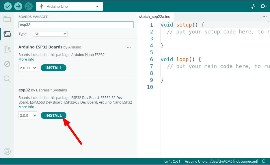
Para poder programar estas placas con el Arduino IDE necesitamos instalar sus definiciones. Lo podemos hacer abriendo la ventana Boards Manager (Tools → Board → Boards Manager...), allí buscamos el término esp32 y picamos el botón Install en las placas esp32 by Espressif Systems.
En algunas versiones de windows hemos encontrado que es necesario instalar un driver para poder comunicarnos correctamente con la placa. Antes de hacerlo asegúrate de que no puedes comunicarte con la placa siguiendo las instrucciones en la siguiente sección.
Si necesitas instalarlo, lo puedes bajar de la página de Silabs
Probando la placa
Una vez que la instalación haya concluido para estar seguro de que todo funciona correctamente podemos programar nuestra placa con el ejemplo Blink:
- Conectamos la placa con el cable USB a nuestro ordenador.
- Abrimos el código de ejemplo Blink (File → Examples → Basics → Blink)
- Para que este código funcione con esta placa, antes de la función void setup() hay que agregar una línea con el texto:
#define LED_BUILTIN 1
Así debería quedar tu código
#define LED_BUILTIN 1

// the setup function runs once when you press reset or power the board
void setup() {

etc...
- Seleccionamos la placa ESP32 Dev Module (Tools → Board → ESP32 → ESP32 Dev Module).
- Seleccionamos el puerto correcto (el nombre del puerto varía según el sistema operativo). (Tools → Port )
So ni sabes cuál es el nombre del puerto puedes revisar el menu antes de conectar la placa, y volverlo a abrir una vez conectada, el puerto que aparezca será el correcto.
- Y por último hay que subir el código (Sketch → Upload ) o picar el botón de Upload (la flecha apuntando hacia la derecha.)
Si todo funciona correctamente deberíamos ver el led de la placa prendiéndose y apagándose cada segundo.
Si subir el código a la placa es muy lento en tu ordenador, prueba a cambiar la velocidad a 921600 en el menu Tools → Upload Speed
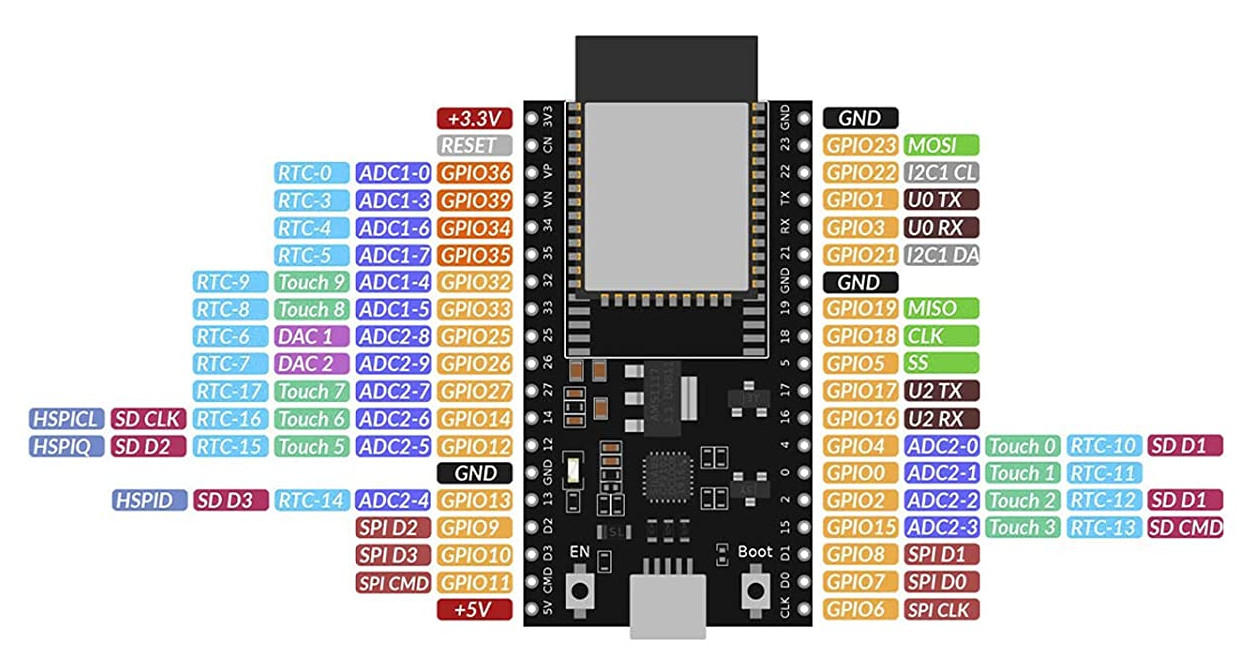
Input/Output
Cualquier pin marcado como GPIO se pueden usar como input/output usando las funciones DigitalWrite() y DigitalRead().
DigitalWrite()
void setup() {
  pinMode(BUILTIN_LED, OUTPUT);     // Initialize the BUILTIN_LED pin as an output
}

// the loop function runs over and over again forever
void loop() {
  digitalWrite(BUILTIN_LED, LOW);   // Turn the LED on (Note that LOW is the voltage level
                                    // but actually the LED is on; this is because
                                    // it is acive low on the ESP-01)
  delay(1000);                      // Wait for a second
  digitalWrite(BUILTIN_LED, HIGH);  // Turn the LED off by making the voltage HIGH
  delay(2000);                      // Wait for two seconds (to demonstrate the active low LED)
}
DigitalRead()
// You can try a digital input with a push button connected to pin D4 (GPIO 2)
int pushButton = D4;

// the setup routine runs once when you press reset:
void setup() {
  // initialize serial communication at 9600 bits per second:
  Serial.begin(115200);
  // make the pushbutton's pin an input and activate the internal pullup resistor:
  pinMode(pushButton, INPUT_PULLUP);
}

// the loop routine runs over and over again forever:
void loop() {
  // read the input pin:
  int buttonState = digitalRead(pushButton);
  // print out the state of the button:
  Serial.println(buttonState);
  delay(1);        // delay in between reads for stability
}
AnalogRead()
Todos los pines marcados como ADC se pueden utilizar como input analógico y nos darán una resolución de 12 bits, esto es valores entre 0 y 4096.
// the setup routine runs once when you press reset:
void setup() {
  // initialize serial communication at 115200 bits per second:
  Serial.begin(115200);
}

// the loop routine runs over and over again forever:
void loop() {
  // read the input on analog pin 0:
  int sensorValue = analogRead(32);
  // print out the value you read:
  Serial.println(sensorValue);
  delay(1);        // delay in between reads for stability
}
Los pines marcados con ADC2 no se pueden utilizar al mismo tiempo que el WiFi, así que si pensamos utilizar el WiFi, tenemos que elegir un pin marcado como ADC1.
AnalogWrite()
Para escribir un valor analógico usamos PWM con la instrucción AnalogWrite()
int led = D4;           // the PWM pin the LED is attached to
int brightness = 0;    // how bright the LED is
int fadeAmount = 5;    // how many points to fade the LED by

// the setup routine runs once when you press reset:
void setup() {
  // declare pin to be an output:
  pinMode(led, OUTPUT);
}

// the loop routine runs over and over again forever:
void loop() {
  // set the brightness:
  analogWrite(led, brightness);

  // change the brightness for next time through the loop:
  brightness = brightness + fadeAmount;

  // reverse the direction of the fading at the ends of the fade:
  if (brightness <= 0 || brightness >= 255) {
    fadeAmount = -fadeAmount;
  }
  // wait for 30 milliseconds to see the dimming effect
  delay(30);
}
WiFi
Con este ejemplo podemos probar a conectarnos a una red WiFi. Recuerda cambiar el ssid y el password
#include <Arduino.h>
#include <WiFi.h>

void setup() {

  Serial.begin(115200);
  WiFi.begin("ssid", "password");

  while (WiFi.status() != WL_CONNECTED) {
    Serial.println("Wifi connecting...");
    delay(500);
  }
  Serial.println("Wifi connected");
  Serial.print("IP Address: ");
  Serial.println(WiFi.localIP());
}

void loop() {
  // put your main code here, to run repeatedly:
}
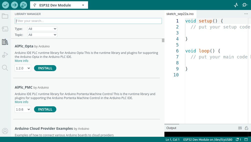
Instalar librerías
Para instalar librerías abrimos la ventana Arduino library manager (Sketch → Include Library → Manage libraries.) o clickando el botón de la izquierda con un ícono de libros.
Arduino Language Reference
AZ delivery ESP32 Hoja de datos
AZ delivery ESP32 Pinout